I. Understanding SuperPOD Construction
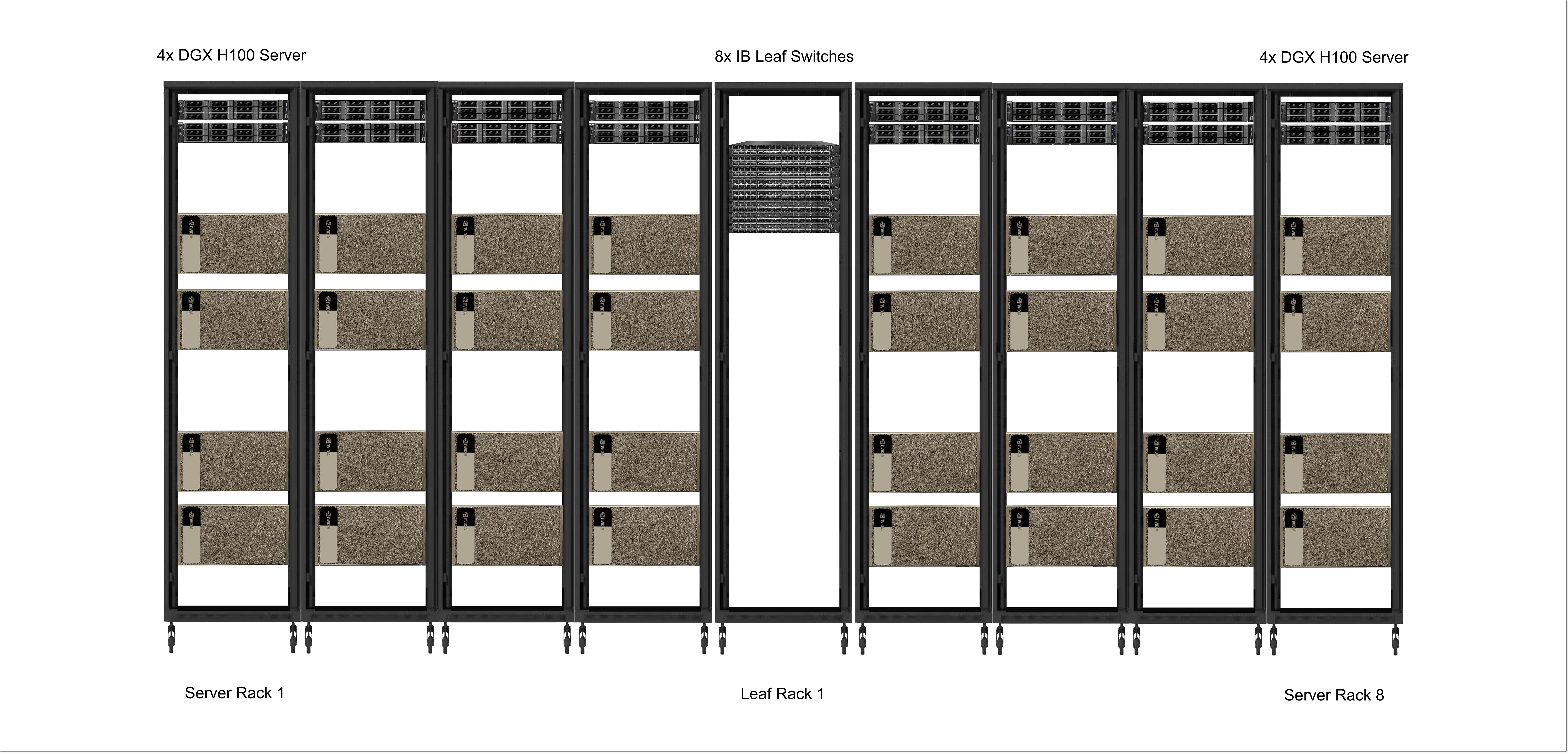
Figure.1 Scalable Unit (SU)
In H100 computing cluster systems, a Scalable Unit (SU) is typically used as the basic management unit. Each SU contains 32 DGX H100 servers distributed across 8 racks, totaling 256 GPUs, and is equipped with 8 Leaf switches (shown in Fig. 1). The server racks are organized in groups of four, positioned on the left and right sides of the Leaf switch rack respectively.
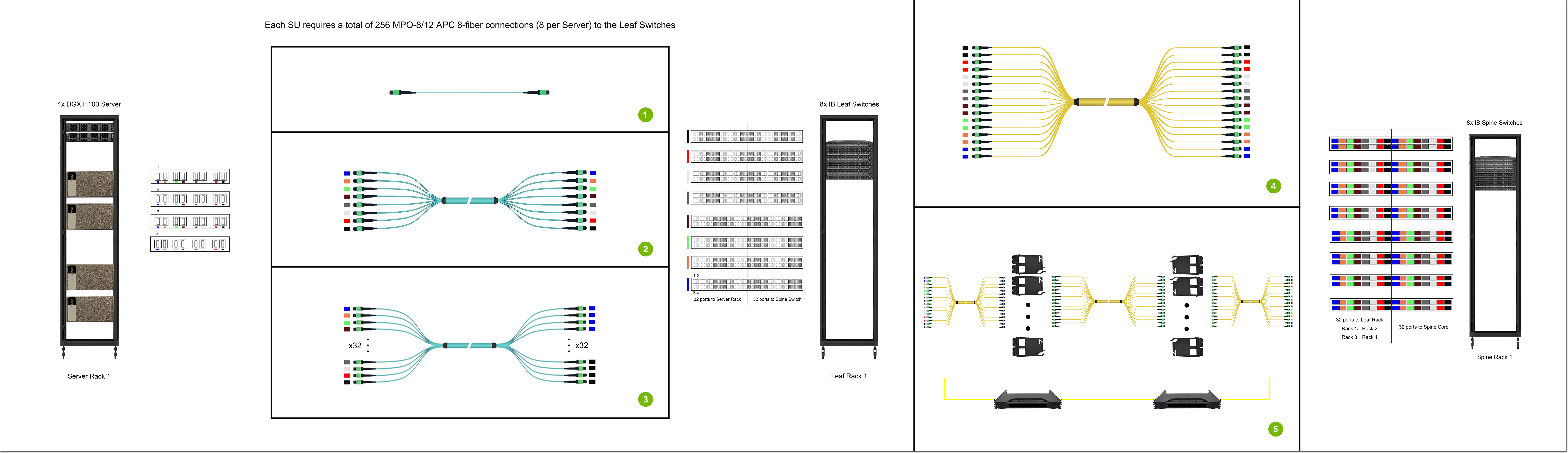
Figure .2 Computing Cluster Cabling
Cabling from servers to Leaf switches and then to Spine switches (shown in Fig. 2) is the core design for building high-bandwidth, low-latency, and scalable data center networks, commonly known as the Spine-Leaf architecture. Within an SU, the distance between servers and Leaf switches is short (typically within a few to dozens of meters), making multimode fiber (MMF) patch cords or DAC high-speed cables the preferred choice for point-to-point cabling. The distance between Leaf and Spine switches is longer (from hundreds of meters to several kilometers), requiring single-mode fiber (SMF) for point-to-point or structured cabling, depending on specific project requirements.
II. Server to Leaf Switch (Point-to-Point Cabling)

Figure 3. Connection in Scalable Unit
Cabling from servers to Leaf nodes (shown in Fig. 3) utilizes either trunk or breakout patch cords. The goal is to connect the corresponding colored interfaces of each server to the Leaf switch of the same color (shown in Fig. 4). For example, the blue interfaces of the four servers will connect to ports 01-04 of the blue-coded Leaf switch. A single Leaf switch provides 32 ports for server connections, while the remaining 32 ports are used for Spine switch uplinks. A switch rack composed of 8 Leaf switches enables non-blocking access for 32 DGX H100 servers.
Figure 4. The cabling selection between the Server and the Switch
III. Leaf Switch to Spine Switch (Structured Cabling)
Figure 5. Connections between different units
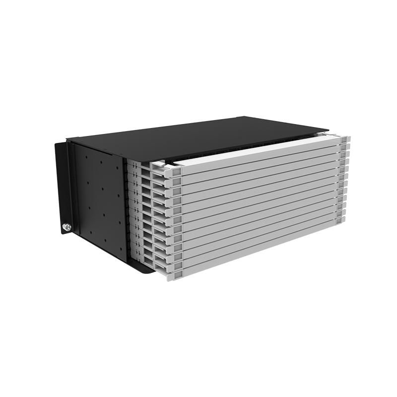
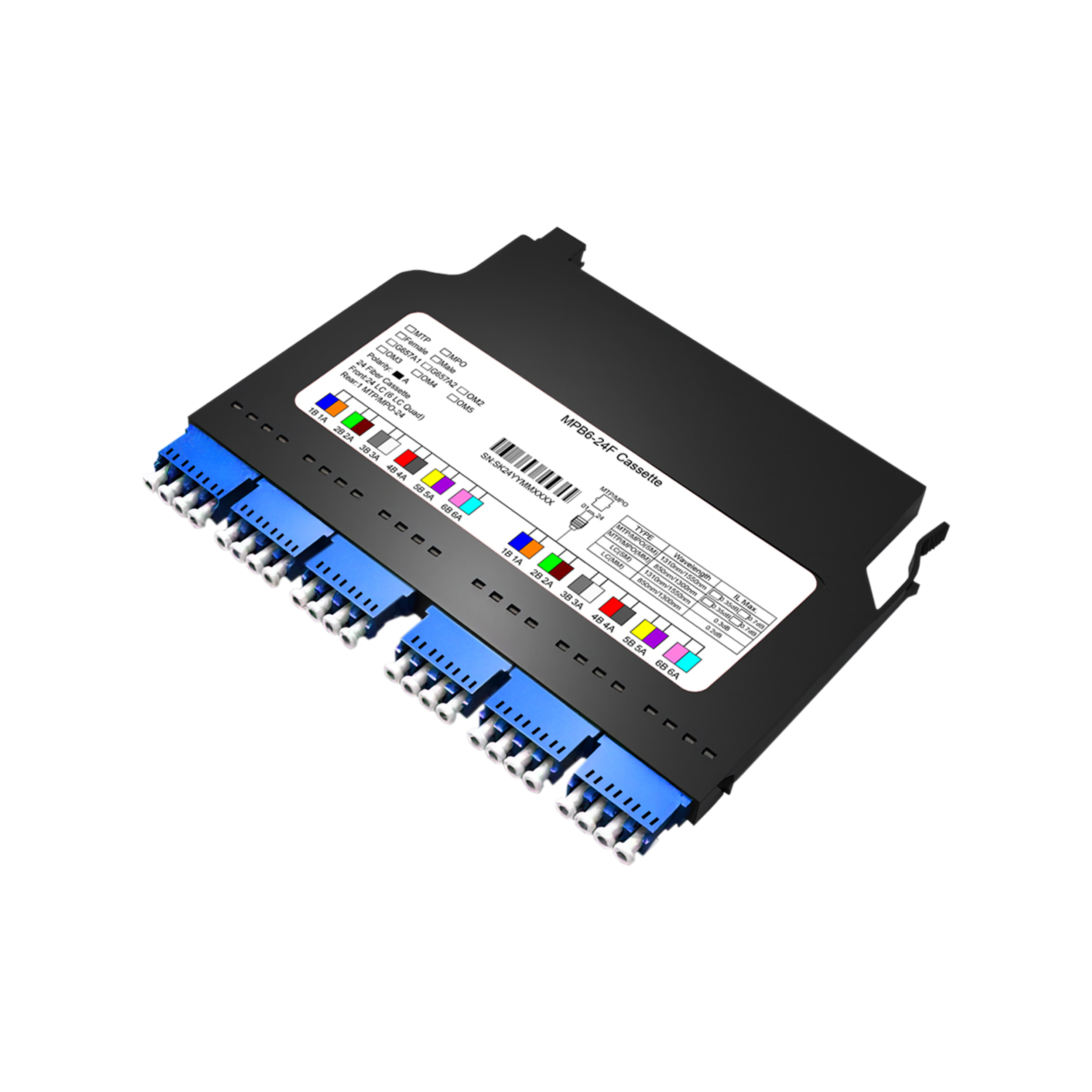
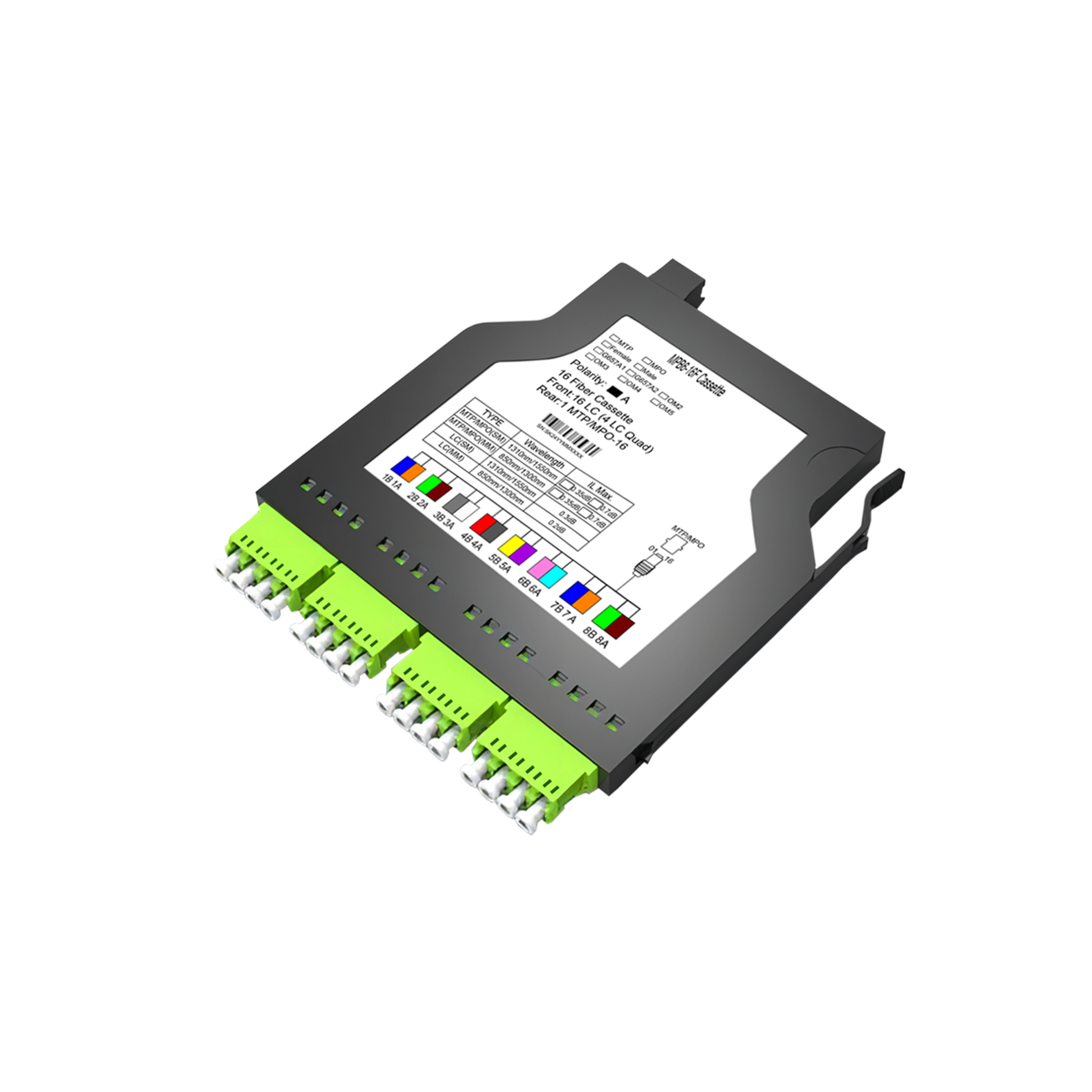
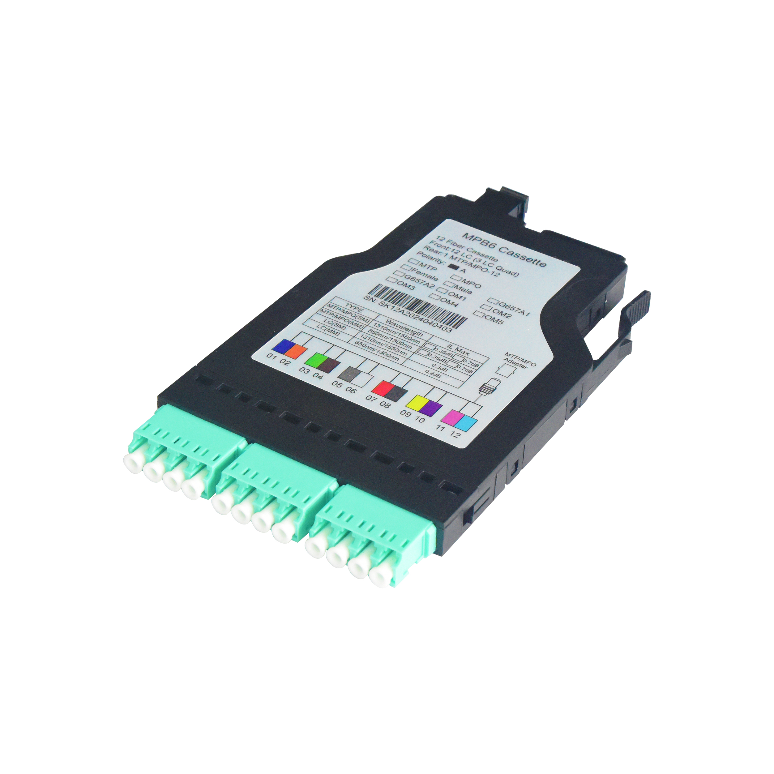
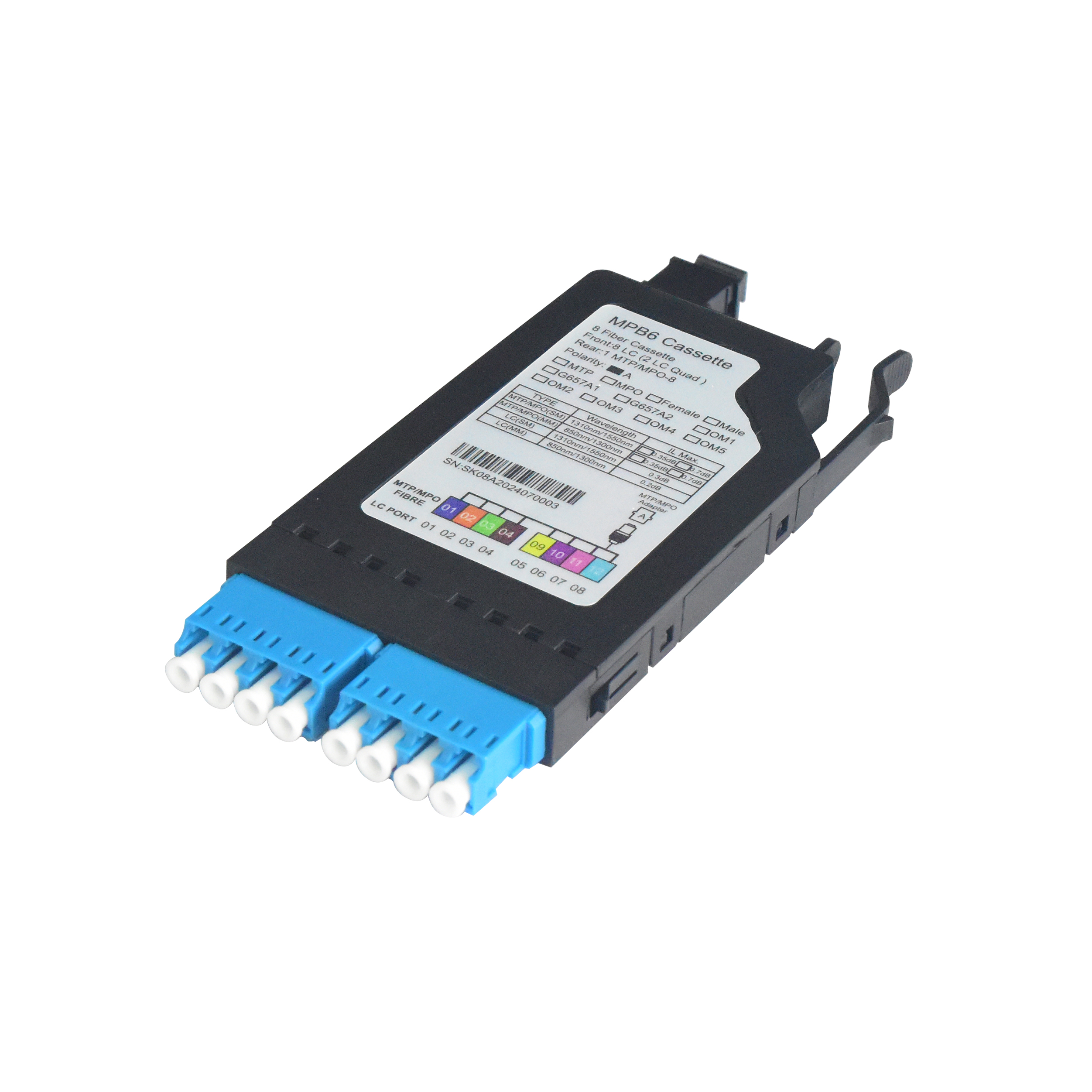
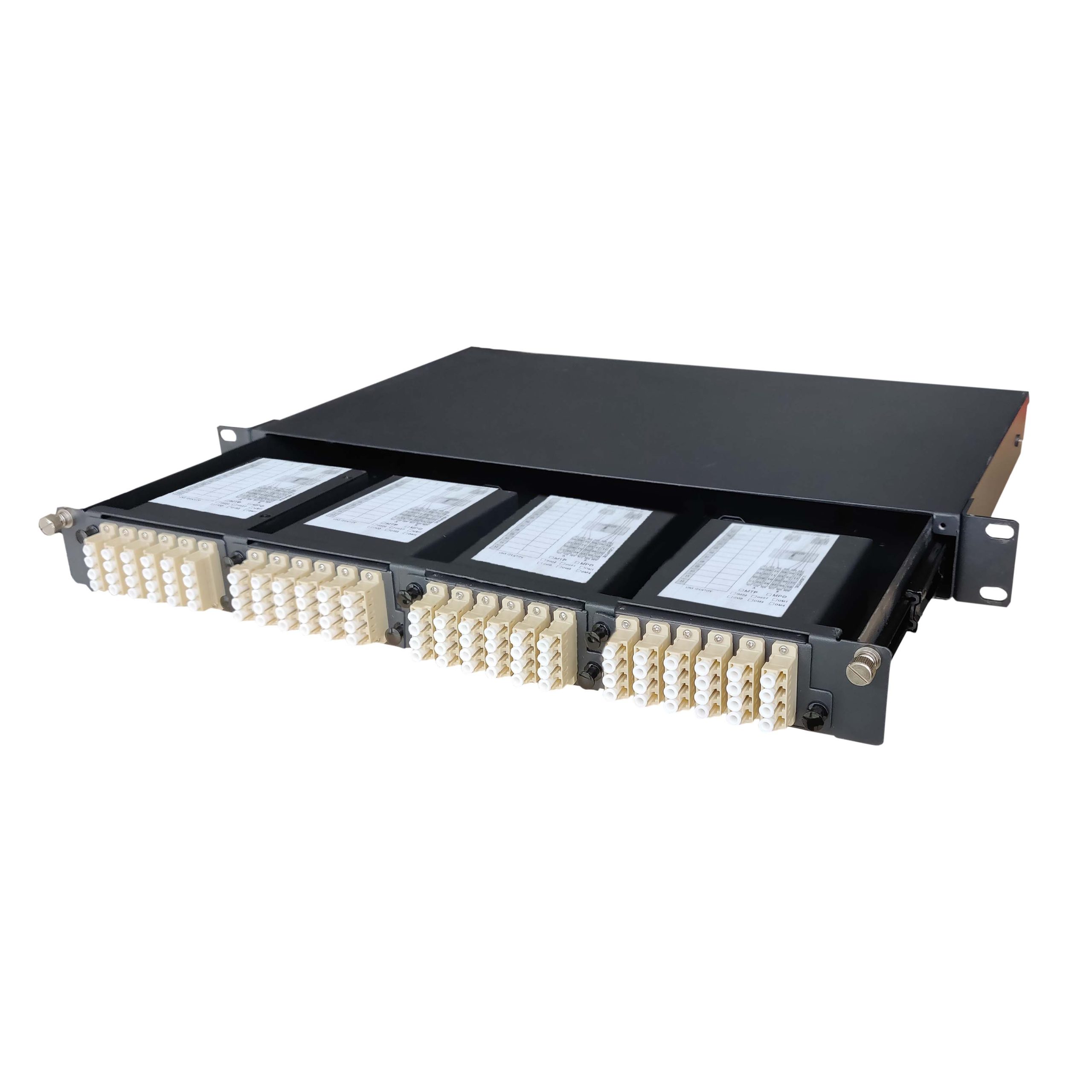
For inter-unit cluster networking (shown in Fig. 5), besides using patch cords for point-to-point cabling, we can also implement structured cabling using patch panels and cassette (shown in Fig. 6). By mapping all ports from the Spine/Leaf nodes onto adapter modules, and the other node connects to the corresponding ports on the patch panel to complete the link. Structured cabling offers significant advantages in centralized distribution and management for large-scale clusters. The labeling system on patch panels makes fault isolation, link tracing, and capacity management more efficient. Through patch panel cross-connects, equipment can be easily added, removed, or reconfigured without altering the backbone lines, supporting flexible resource scheduling.
Figure 6. The cabling selection between the Leaf Switch and Spine Switch
IV. Product List
Fiber Opitic Patch Panel
MPO Cassettes
MPO Cables
Structured Cabling Deployment